Arc Blast:
Electric Carving of Planet Earth

- By Andrew Hall
Or look at a telescope image of planetary nebula and recognize the hourglass shape of plasma current contracting to form a star.
Or view the red-shifted quasars inside Halton Arp’s “unusual galaxies” and determine if they are really the distant objects we’re told by conventional astronomy.
In fact, through Electric Universe eyes, it is clear that the patterns in nature, from galactic to nuclear, are coherent, fractal, and electric.
The planets and moons of the solar system provide some of the most accessible and compelling visual evidence of all. Hexagonal craters, rilles and the odd distribution of these features, often concentrated near the poles, or in one hemisphere, attest to an electrical formation. One can imagine the vortex of discharging plasma that carved them.

The central pillar of Mt. Fitzroy
Earth should also show electrical scarring. In an Electric Universe it must be the case. But it is not intuitively apparent.
Unlike the Moon, or Mercury, Earth does not display a carpet of hexagonal craters. There are some craters that are ancient and eroded, but their formation remains controversial.
There does exist proof of electrical scarring on Earth, however, and it is in abundance. As a matter of fact, it is staring us in the face. This Thunderblog will discuss how to recognize it.
First however, recognize that what distinguishes Earth from a planet like Mercury, or the Moon, is its atmosphere and geomagnetic field. This changes the electrical character of the Earth entirely. It does not respond like a bald, rocky planet in an electric current, drawing lightning bolts from a region of space that carries a different electrical potential.
Earth acts like a gas giant, integral to the circuitry, with current flowing through as well as around it. But Earth’s current flows in a liquid plasma — the molten magma below the crust. In the event the system is energized, current discharges from within.
The evidence is in the extensive volcanism on Earth. Volcanoes straddle subduction zones at the edges of continental plates, rift zones and mid-ocean ridges. They betray the flow of current beneath the crust.
Surface evidence is in the mountains. Basin and range, mountain arcs, and mountain cordilleras are all proof of electrical discharge. To understand the visual evidence, however, requires looking beyond the simple concept of a lightning bolt from space. The reason is the Earth’s atmosphere.
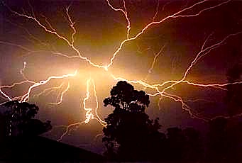 When electrical discharge occurs in an atmosphere, it creates sonic-hydrodynamic effects. We experience the effect when we hear thunder — the sonic boom of a lighting bolt. It is the sonic and hydrodynamic effects, in a dense, viscous atmosphere, that leave its mark on the landscape at the grandest scale.
In a previous Thunderblog, “Surface Conductive Faults,” the concept of a surface conductive double layer providing a path for arc flash was shown. The surface conductive path is the cloud layer where ions collect to produce thunderstorms.
Imagine a lightning bolt of immense proportions, sheets of lightning, in fact, arcing horizontally in this region that is roughly five to fifty thousand feet above the land. The focus of this article is the hydrodynamic effects of the resulting arc blast. Arc blast is the consequence of arc flash in a surface conductive current discharge.
Four Steps to Build a Mountain . . .
The following image (annotated by the author) from Los Alamos Laboratories shows a shock wave being created by a supersonic projectile passing over water. The colors display density: highest in the red, lowest in the blue. Purple is the baseline of the atmosphere. It provides a very good analogy for the way a mountain is built.
The result of the arcs passing is embossed on the land by shock waves that act almost precisely as those made by the projectile.
The difference being the shock wave is plowing land, not water, and it has the hyper-sonic velocity, heat and power of an arcing current — much more energy than a simple projectile.

The bow shock is an anvil of many thousands of psi at a temperature many times that of the sun, carrying charged electric fields. In a dense, viscous environment, fluid mechanics, shock effects and electromagnetism align in phase and frequency with the arc that creates them.
In Region 1, the bow shock vaporizes, and melts the ground, plowing an oblong crater.

Region 2 is a reflected shock wave blasting into the atmosphere, pushing an exploding cloud of vaporized debris into a Richtmeyer-Meshkov instability, more commonly known as a “mushroom cloud.”
The cloud is not shown in the projectile over water because that simulation did not involve the explosive effects of expanding gases heated instantaneously by an arc flash.
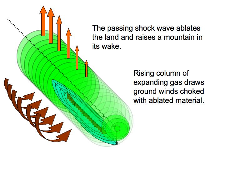
The mushroom cloud rises behind the shock wave with a supersonic vacuum at its core. The updraft of expanding gases generates in-flowing ground winds that scream like banshees across the ablated surface of the blast zone, attaining supersonic speeds as they funnel to the core of the updraft, dragging clouds of molten rock and dust. A simulation of such an event created by an air-burst meteor is portrayed in this video by Dr. Mark Boslough of Sandia Labs.
The ground winds are directed perpendicular to the primary shock wave. Keep this in mind, because it is very important evidence in the geometry of mountains.
In Region 3, a low pressure updraft forms, like the rooster tail behind a speedboat. The rooster tail pulls ablated melt from the crater. It forms the core of the mountain.
In Region 4, multiple shock reflections form triangular wave-forms. Note, the reflected wave bounces from the surface. The base of the triangle forms on the surface that reflects it.
The multiple shock reflections in Region 4 are standing waves. Standing waves don’t travel. The wave-form stays in place with the energy coursing though it. Reflected waves multiply, like in a hall of mirrors, repeating harmonic wave-forms to the nth degree, until the energy of the shock dissipates.
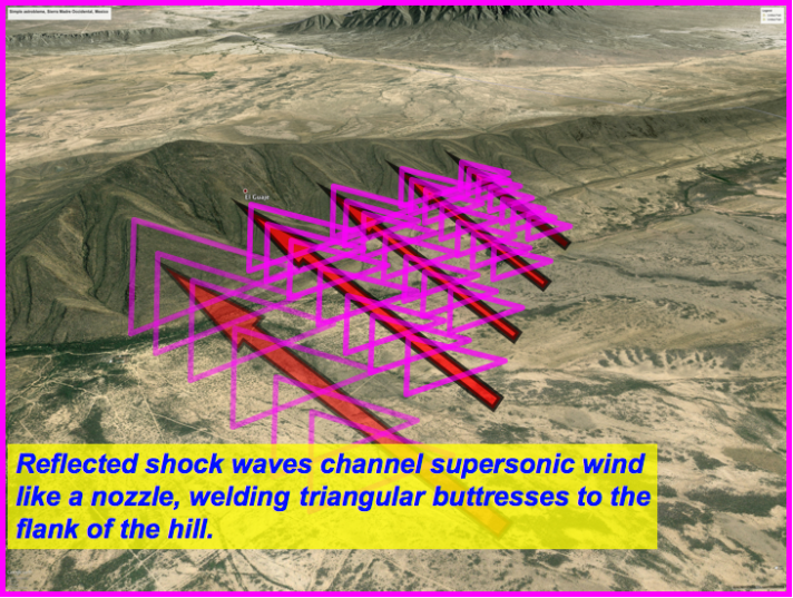
 The reflected shock waves are rigid and stable when the energy is high, creating a shock ‘envelop’ over the ablated land. The energy does not dissipate quickly, because the vacuum of the mushroom cloud above is punching a hole through the atmosphere to space, drawing supersonic winds through the shock envelope like a cosmic vacuum. This is a source of free energy to the shock wave that keeps it alive.
Shock waves are highly energetic. They are razor thin sheets of pure energy, entire tsunamis in a sheet of glass. Like steel plates animated with resonate energy that derives from the original bow shock.
The incoming ground winds funnel through triangular plenums formed by reflected shock waves. The entire envelop of reflected waves acts as a coherent entity, with structural stiffness, resonating with the vibrations of the parent shock and the supersonic winds screaming through it.
It rides on the surface of the land, spread across the entire impact zone of the bow shock, like a multi-manifold vacuum cleaner, hosed to a hole in the sky above.
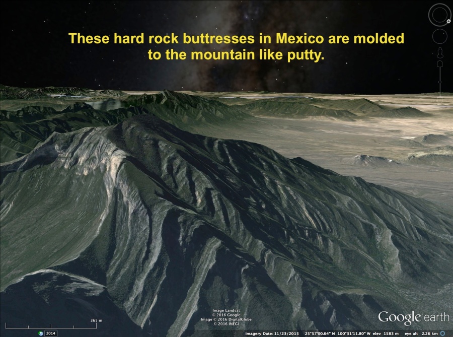
The winds plaster the mountain core with layered triangular buttresses.

Supersonic Wind Effects . . .
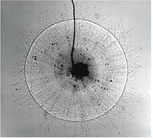
Reflected shock waves from a bullet impact
Shock reflections form at 90 degrees to the path of the shock wave that made them. Therefore, they emanate radially from the impact as seen in the Schlieren image of a bullet impact.
Hence, the orientation of triangular wave-forms holds information on the path of the initial shock.
It also vectors the supersonic wind flow, which layers the buttress in place. Therefore, wind direction is perpendicular to the stratified layers of the buttress and can be determined.
Examination of the coherent orientation of triangular buttresses dispels any notion they were made by random influences of wind and rain over the eons. The non-random, radial orientation of wave-forms is, in fact, impossible to explain except as the result of a single shock event that produced winds unlike anything we experience today.
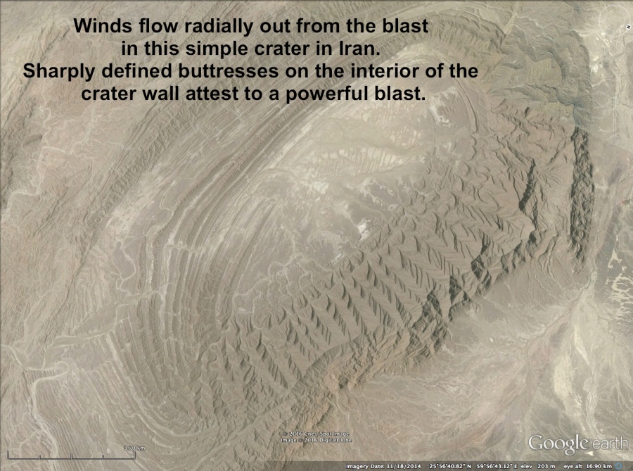


When a shock wave dissipates, the inflow of winds doesn’t necessarily stop, but they slow down and are no longer constrained to the path formed by the shock fronts. The final layers of material deposited often lose coherence and exhibit sub-sonic flow patterns.

The layered material on buttresses is deposited in a hot, molten state. Patterns of deposition display evidence of molten fluidity at the time they were made.
Reflected Shock Waves . . .

 Supersonic shock waves display particular behaviors that have been studied by aerospace engineers since the beginning of the jet age. These characteristics must be understood to design airplanes, missiles and rockets. A great deal is known about their behavior.
 The angle that the initial shock wave makes is directly related to the Mach speed of the wave. Thus, it is called the Mach angle. Hence, the Mach angle holds information on the speed of the shock wave that made it. The triangular reflected wave form is an inevitability of supersonic flow. It forms when the initial shock wave hits a surface and reflects.
The reflected wave will have an equal, but opposite angle incident to the surface from the shock wave that made it, assuming the plane of the surface and trajectory of the wave front are parallel.

When the incident angle between the shock trajectory and the reflecting surface change, more reflected waves are created in predictable ways. Hence, the reflected angle holds information on the trajectory of the shock wave that made it.
The amplitude and wavelength of the reflected waves diminish over time as the energy dissipates. Hence, reflected waves hold information on the energy of the event that made them.
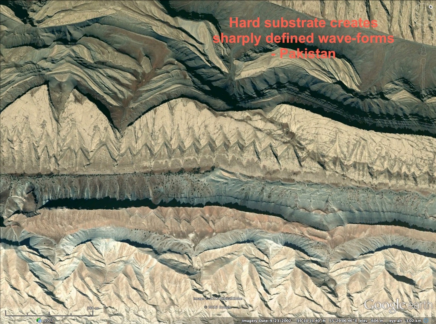
 The shock wave travels on a transverse carrier wave called the “propagating wave.” This vibrates the land, seismically, from the hammer blow of the shock wave. The land will reflect some of the shock and absorb some of the shock, as a function of its modulus of elasticity. Hard rock will reflect better than sandstone because the sandstone will absorb much more of the shock. Uneven surfaces will also modify the wave-form. This contributes to the variety of wave-forms we see.

Supersonic shock waves are longitudinal waves. Instead of vibrating up and down in a sinusoidal vibration, longitudinal waves compress and expand back and forth, like an accordian. Transverse waves, like the propagating wave, travel up and down.


The result is longitudinal and transverse waves super-positioning. Except inverted to the super-positioned wave shown below, with the fixed boundary above, fixed to the point in space the shock originated from, and wave motion amplified near the ground.


The static image in pink shows the standing waveform that results. Compression results in a higher frequency of small amplitude, short wavelengths, and expansion results in low frequency, high amplitude, long wavelengths. Triangular buttresses are the molded product of these shock waves, frozen in time as supersonic winds fused them in place on the mountain core.
Take a look:
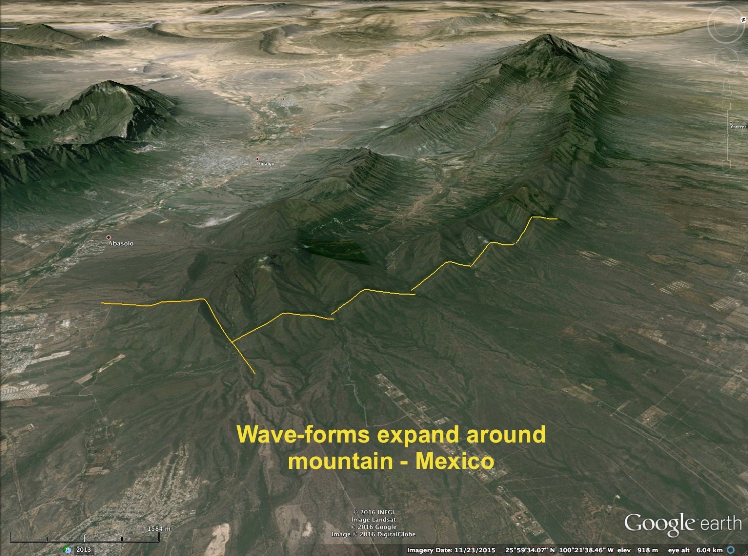


These wave-forms had to be created from above. A wave needs a surface — an interface — with a medium of higher density to reflect. Pure seismic waves shaking and rolling the ground from below are unbounded above. The atmosphere cannot reflect a seismic shock and create a reflected wave-form on a mountain side. The shock waves came from above.
Our ancestors had a name for them . . . Dragons.
Conclusions . . .
1. Triangular buttresses form on the sides of mountains in the shape of reflected supersonic shock waves.
2. They are layered onto the mountain; thus, they are not caused by seismic waves.
3. They are layered perpendicular to the wind direction, consistent with supersonic winds created by shock waves.
4. The triangular wave-forms are parallel to the primary shock pattern, consistent with reflected shock waves.
5. The triangular wave-forms exhibit less energy and more transient effects on softer substrates and higher energy, sharper angles on hard substrates.
6. They are not layered sediments from an ancient beach, or waterway since triangles are a consistent feature around the world and do not conform to any motion of random water waves.
7. They are formed in all types of rock, including granite; thus, they are not formed by eons of normal winds.
8. The triangular wave-forms exhibit compression and expansion from superimposed longitudinal and transverse waves that came from a source above.
Triangular buttresses are an imprint of the Dragon’s teeth, formed by supersonic winds and shock waves caused by an arcing current in the atmosphere. In Arc Blast — Part Two, more evidence of the hydrodynamic forces that shaped our planet will be examined.
1. Evidence of harmonic resonance
2. Effects of wave super-positioning and cancellation
3. Normal shocks and features of density variation and expansion fans
4. Boundary layer features of reflected waves in the substrate of the blast zone
https://youtu.be/mPcF40vBqzs
Electric Universe Geology: A New Beginning | Space News

…We looked at how arc blast from current in the atmosphere could produce supersonic shock and wind effects that create a mountain. We examined triangular buttresses on mountainsides that exhibit the characteristic standing wave-form of a reflected shock wave. In particular, we looked at how they are layered perpendicular to the wind direction, and exhibit compression and expansion from superimposed longitudinal and transverse waves that came from a source above.
We now examine more, compelling evidence.
Harmonics . . .
The images below are color enhanced Schlieren photographs of reflected shock waves in a wind tunnel.
Wind tunnels typically show supersonic flow between two surfaces. The initial shock reflects from both walls, creating two triangular wave-forms adjacent to each other. The diamond patterns that form between the triangles are often called ‘shock diamonds’.
In the case where a supersonic shock wave is created in the air, it is unbounded above, so the only surface reflecting it is the ground, and it creates a row of triangles instead of two opposing rows.
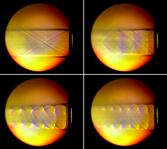
The initial wind speed in the first frame (top left) is Mach 2. It shows the shock wave producing one and a half diamonds.
The wind tunnel is charged with gas in a pressure vessel. So, as the gas flow progresses, the pressure and mass flow decrease from the pressure vessel, lowering the Mach speed of the wind.
The subsequent frames shows instability in the shock waves as the winds slow. The wave-forms compress and the angles of the primary and reflected waves grow less acute.
Vertical shock waves form, called normal shocks, which travel through the triangles, distorting their shape where the normal wave crosses the reflected wave, causing more reflections. New smaller triangles form and replace the original standing wave. This is harmonic reflection of the primary shock wave.
In the final frame (bottom, right) the wind speed has slowed, the triangular wave-forms are smaller and higher frequency. There are seven shock diamonds where there were initially one and one half.
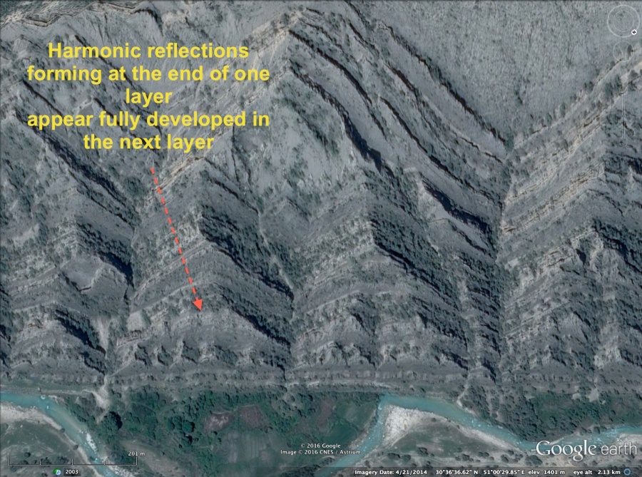
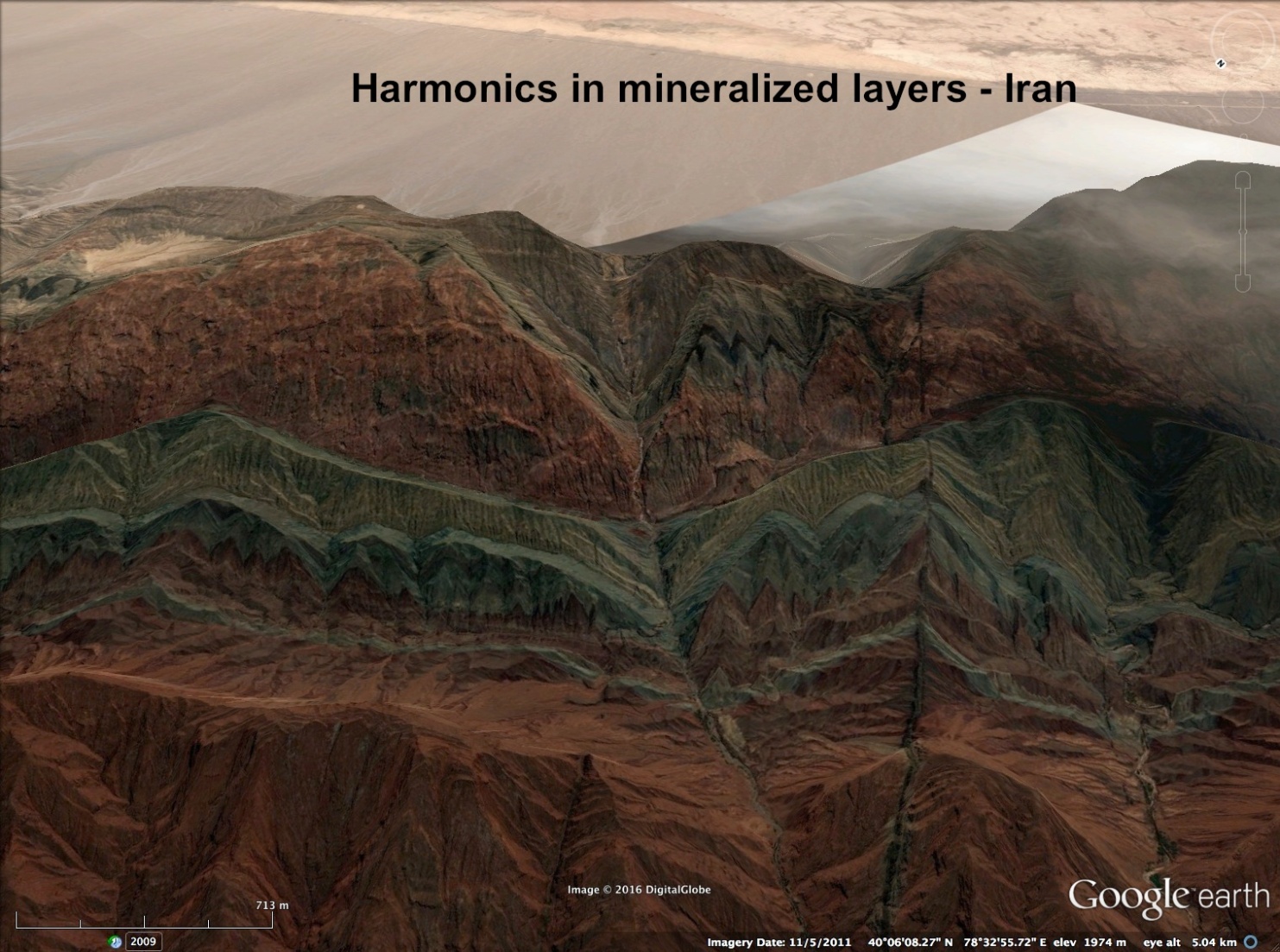
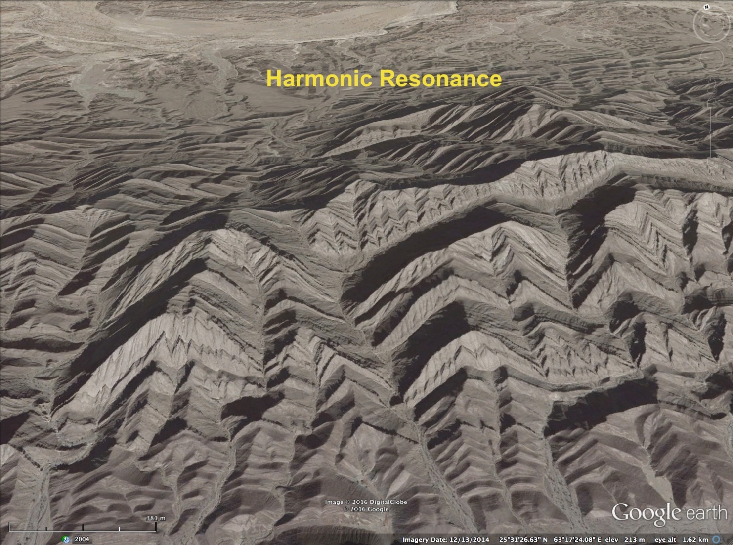
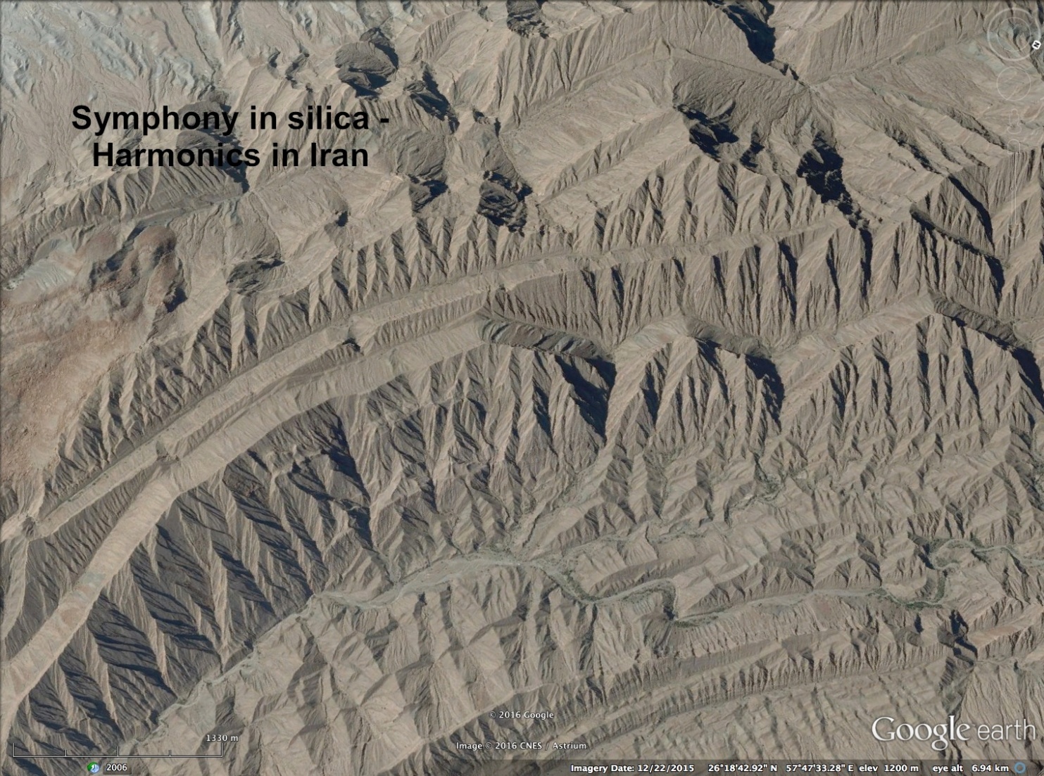
This sequence of harmonic reflection as the energy of the shock wave dissipates is evident on the triangular buttresses stacked on the sides of mountains. As seen in the images below, triangles are stacked upon triangles in harmonic multiples as the successive layers of material were deposited by supersonic winds, tunneled by the reflected shock waves.
The first image in this group is most instructive. In it, the lower-most layers of harmonic waveform can be seen to have begun to form at the outer edge of the preceding layer.

Instability, Interference and Cancellation . . .
 Transients in wind speed, Mach angle and multiple reflections create instabilities in the wave-forms. Unstable waves segregate and fan away from each other under expansion, fragmenting the wave-forms.
Or they bunch together in compression, pressing waves against each other. Shock waves don’t cross, but fold against each other, like magnetic fields interfering.
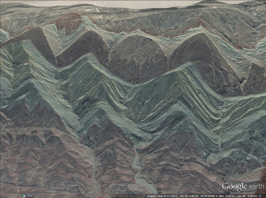
As wave-fronts compress, the wave-form can be squeezed and cancelled-out. In this image of a mountain in Iran, three wave-forms compress, distorting into curves where the waves, pressed against each other, bend the center wave-form almost circular. In the following layers, the pinched wave has cancelled altogether and the surrounding wave-forms have joined, stretching wavelengths to close the gap.
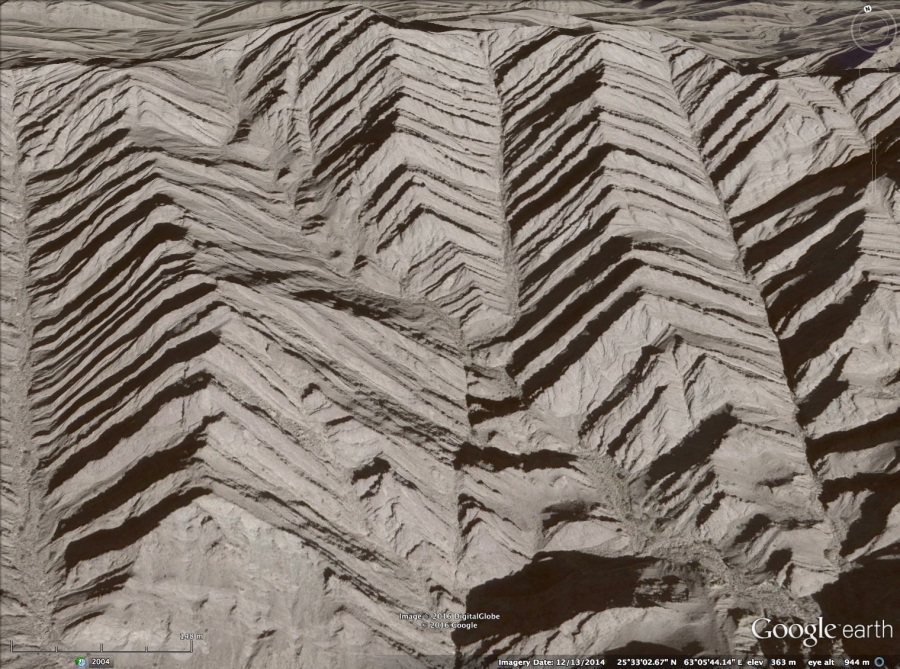
A similar wave cancellation has occurred in the next image. Here the center wave-form is cancelled by neighboring wave-forms, and they have expanded to fill the wavelength. A diagonal shock line appears cutting the mountain where the cancellation occurs. It crosses in a step-wise fashion, a few layers at a time, causing it to zig-zag. Note the ruler straight shock lines that divide the adjacent triangular buttresses.
Complex Wave-forms . . .
Complexity is found within the shock fronts, inside the triangles themselves, as pressure and density variations.

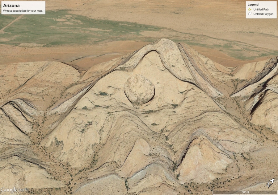
Note the density variations form a circular feature near the top of this Schlieren image. The same feature is on the distorted triangular buttress found in Northern Arizona, shown below.
Also, note how the edges of the triangle draw in towards the circle, just as the waves near the top in the Schlieren image do. The three small buttresses below the hole show a striking similarity to the size and location as those on the wave-forms in the same position in the Schlieren image.
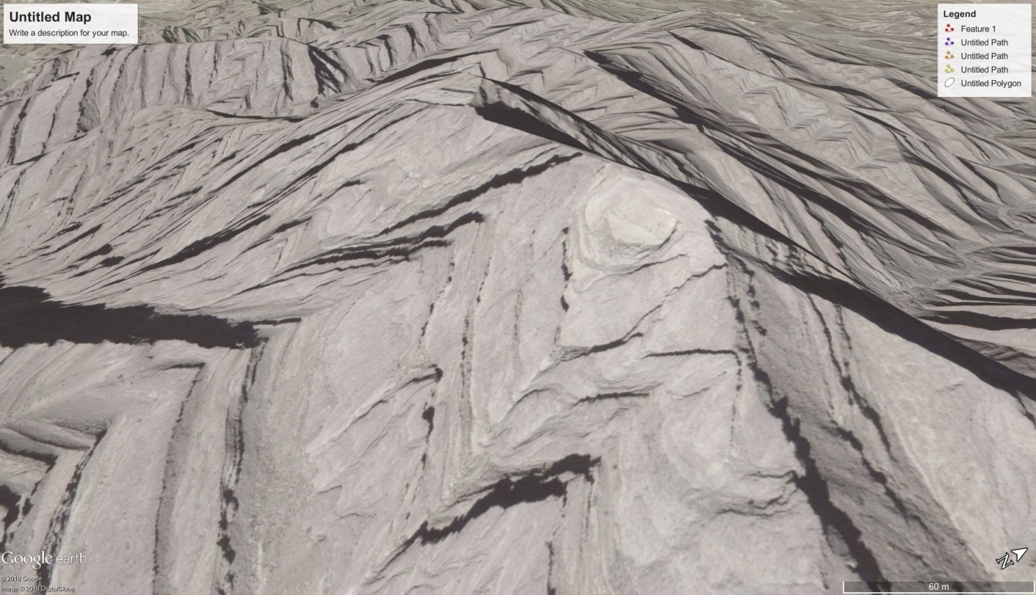
Here is another hole created in a triangular buttress. This one is in Iran.
The Lambda Foot . . .
This road cut is in Iran and is sometimes described as the slip fault that created the ‘horst-graben’ or basin and range region where this is found.
That isn’t the case. This slice in the ground was left by the primary, or incident shock (left side of the ‘V’) and its reflected shock (right side of the ‘V’).
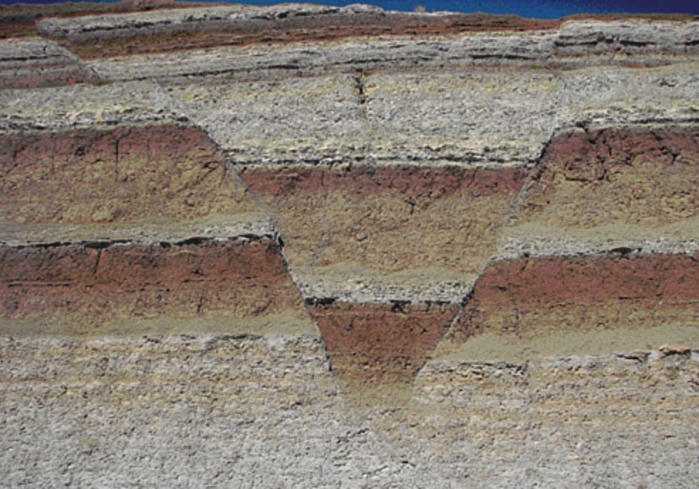
This is the boundary region where the initial shock meets and reflects from the ground. The incident shock curves sharply downward, and the reflected shock is nearly straight. Where the reflected shock and incident shock meet, there is a feature called the lambda foot.
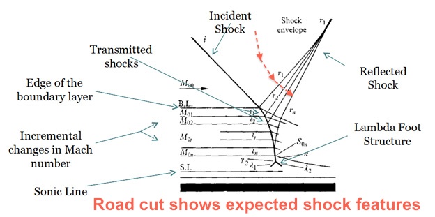
Note, the incident shock curvature and the particular dip of the sedimentary layers within the ‘V’. They are similar to the angled transmitted shocks shown in the ‘V’ of the diagram. Here is another image with a broader view. In this view, the lambda foot is easier to discern.

Also, a feature not originally shown on the diagram, the cut in the center top of the ‘V’ results from a shock that curves downward, normal to the expanding corner of the reflected shock, annotated in red on the “road cut” diagram.
This shock feature is along the side of a hill that can be seen stacking in layers to the left. It should define the outer boundary of the initial shock wave. If so, it should form a ring around the mountain. A similar ‘V’ shaped cut should be found on the opposite side of the hill. If true, the incidence angles, and distance between this ‘V’ and the predicted ‘V’ on the opposite side, hold information about the height of the apex of the passing wave.
Conclusions . . .
Harmonic repetition is undeniably evident on triangular buttresses — proof they resulted from a sonic shock event. It is proof they were created in a single, coherent event, and could not possibly be the result of time and erosion.
The other effects examined are particular to sonic shock waves as well. In Part Three, evidence for electromagnetic effects of the arc blast will be reviewed.

The Angry Photographer – Magnetic Field
…We looked at how arc blast creates a mountain. We examined triangular buttresses on mountainsides and how they conform precisely with the characteristics of reflected shock waves. In particular, we looked at layering, compression and expansion of the wave-forms.
In Part Two, we looked at evidence of harmonics, wave-form instabilities and boundary layer effects that are imprinted on the landscape.
In this article, we’ll take a closer look at layering and electromagnetic influences.
Electromagnetic Effects . . .
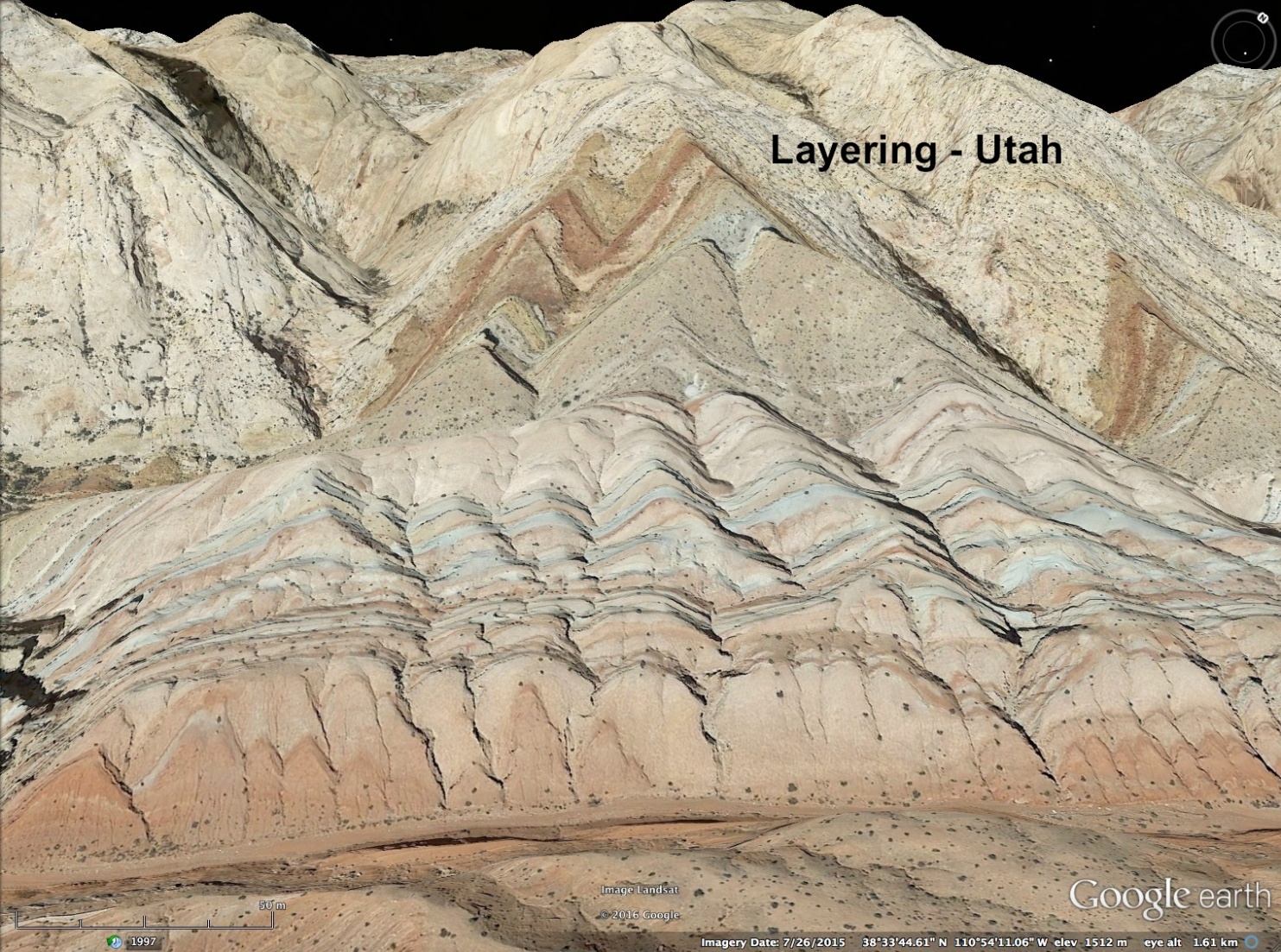
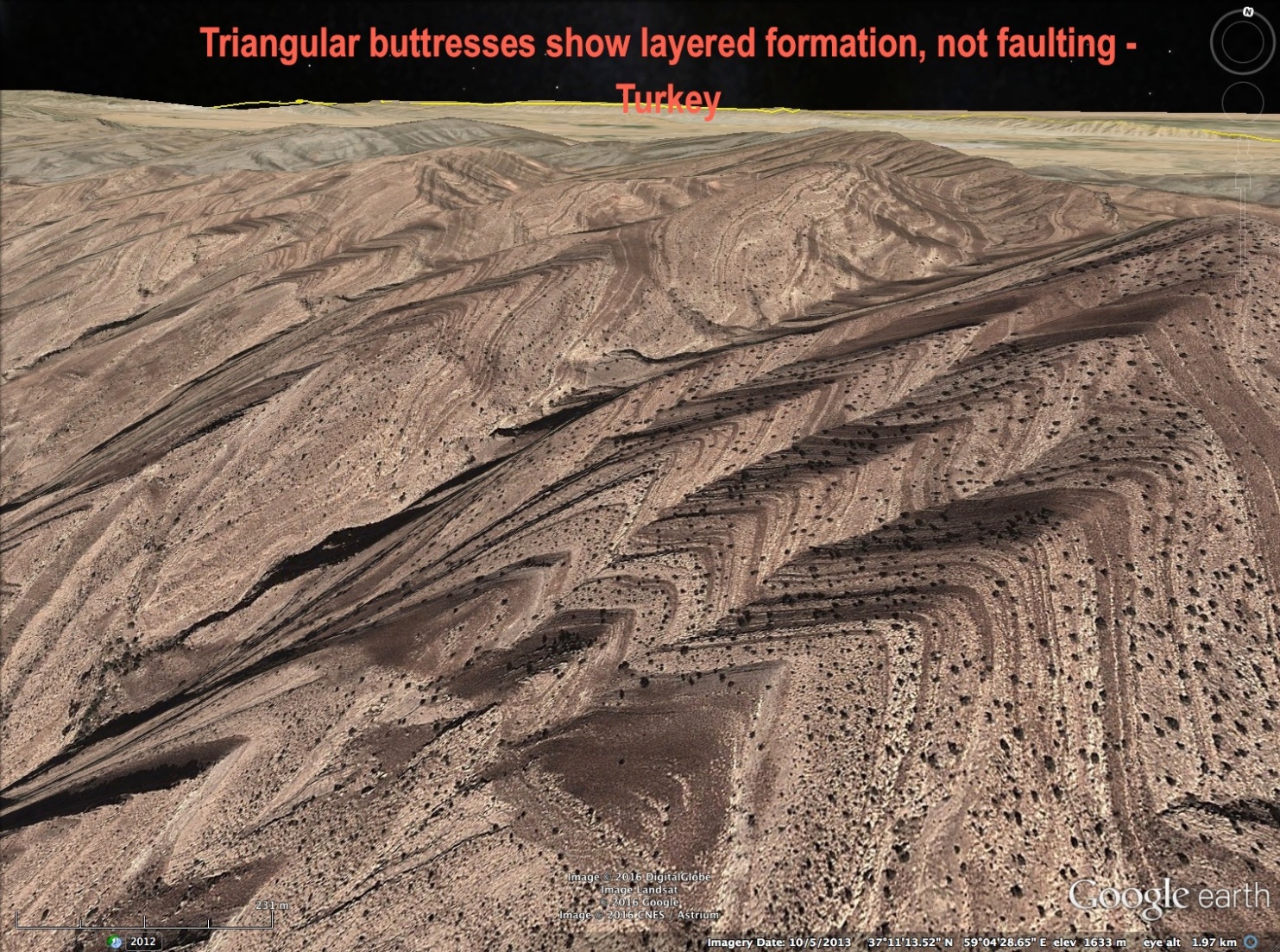
The stratified layers of triangular buttresses are often segregated by mineral composition. This is evidence of electromagnetic forces. The arc flash that creates the mountain is essentially a lightning bolt, traveling in an ionized double layer in the atmosphere. An electric field will ionize particles. A magnetic field will sort them. An arc flash necessarily has an electromagnetic field surrounding it.
In fact, the arc is just the intense current flow of electrons at the core of the electromagnetic field. The field itself expands away from the core with the shock wave.
The shock waves are energized with current. The shock wave is a highly stressed region – a dramatic shear zone of pressure, density and temperature the ionized winds can’t penetrate. Ionized material flows with the winds in the low stress triangular region between the shock waves. The shock wave itself is a conduit for current. Current coursing through thin shock waves molds the electromagnetic fields in the coherent form of the reflected shock and sorts material according to its dielectric properties.


Blowouts . . .
Another dramatic signature of an electrical nature is a feature called a “blowout.” Blowout occurs when the arcing current makes direct contact with the ground.
The arc flash follows the most conductive path available. It travels in the ionized atmosphere, especially in arid regions where soils are dry and non-conductive compared to the ionized atmosphere above ground. When a conductive surface feature is available, the arc will fork to ground.
The conductive feature may be a mineral deposit, or water in a stream, aquifer or wetland. The result is a crater that blasts away a portion of the mountain being formed. The images below show a blowouts in the center of a mountain. It is apparent the crater significantly modified the form of the mountain.


Expansion Fans . . .
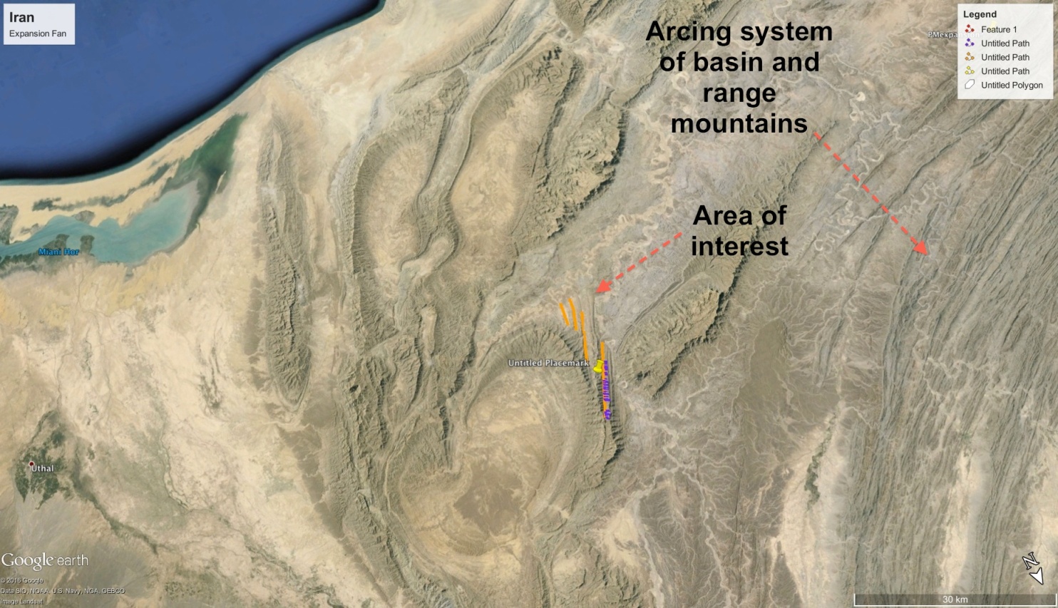
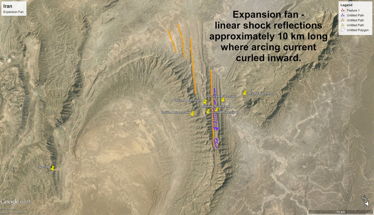
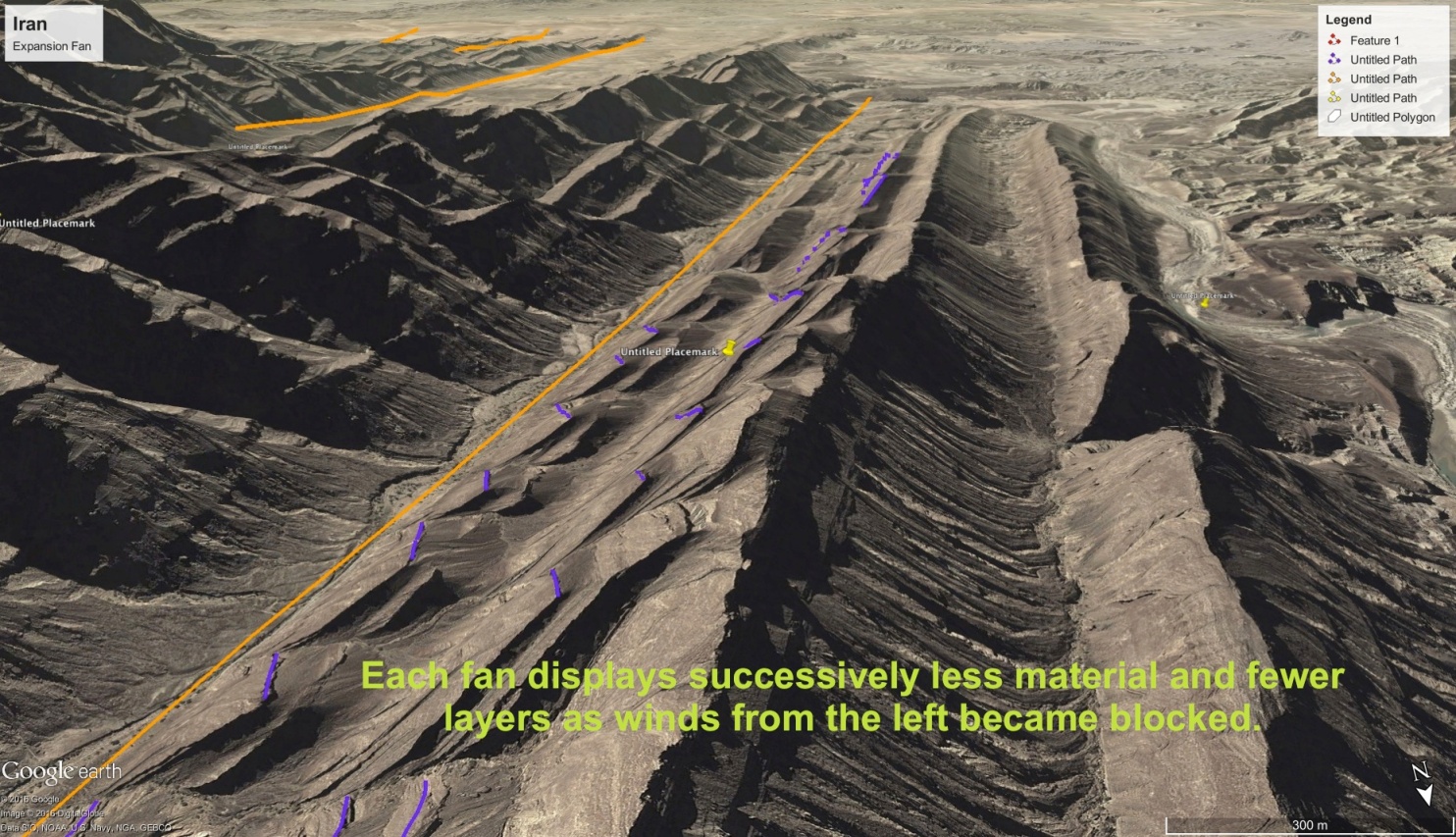
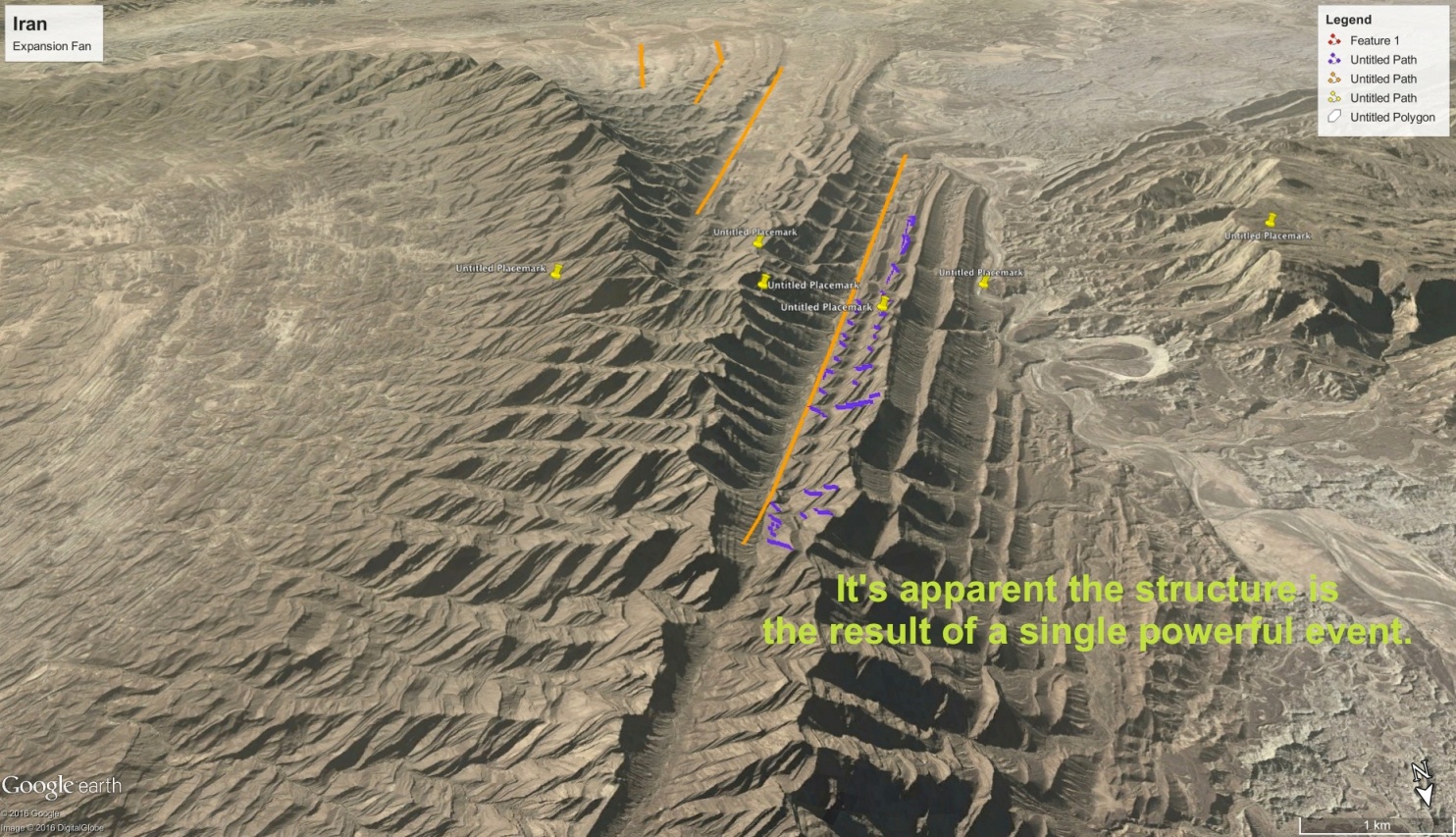
 The images to follow are from a complex formation of astroblemes in Iran. They are on the outside, or convex bend, in a large mountain arc.
One unusual crater shows shock effects as the apparent arc trajectory changes. The feature annotated is an example of an expansion fan, which is a set of reflected waves that occur on the outside of a bend (convex) when the source of the shock makes a change in direction. The fanning shock waves have produced linear hills that radiate from the bend.



Ejecta and Ablation Zones . . .
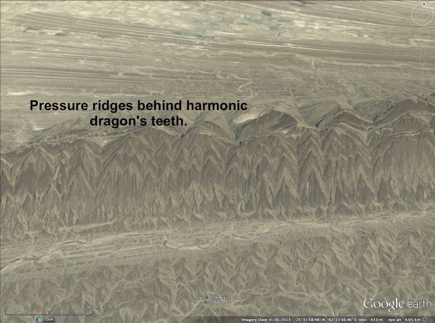
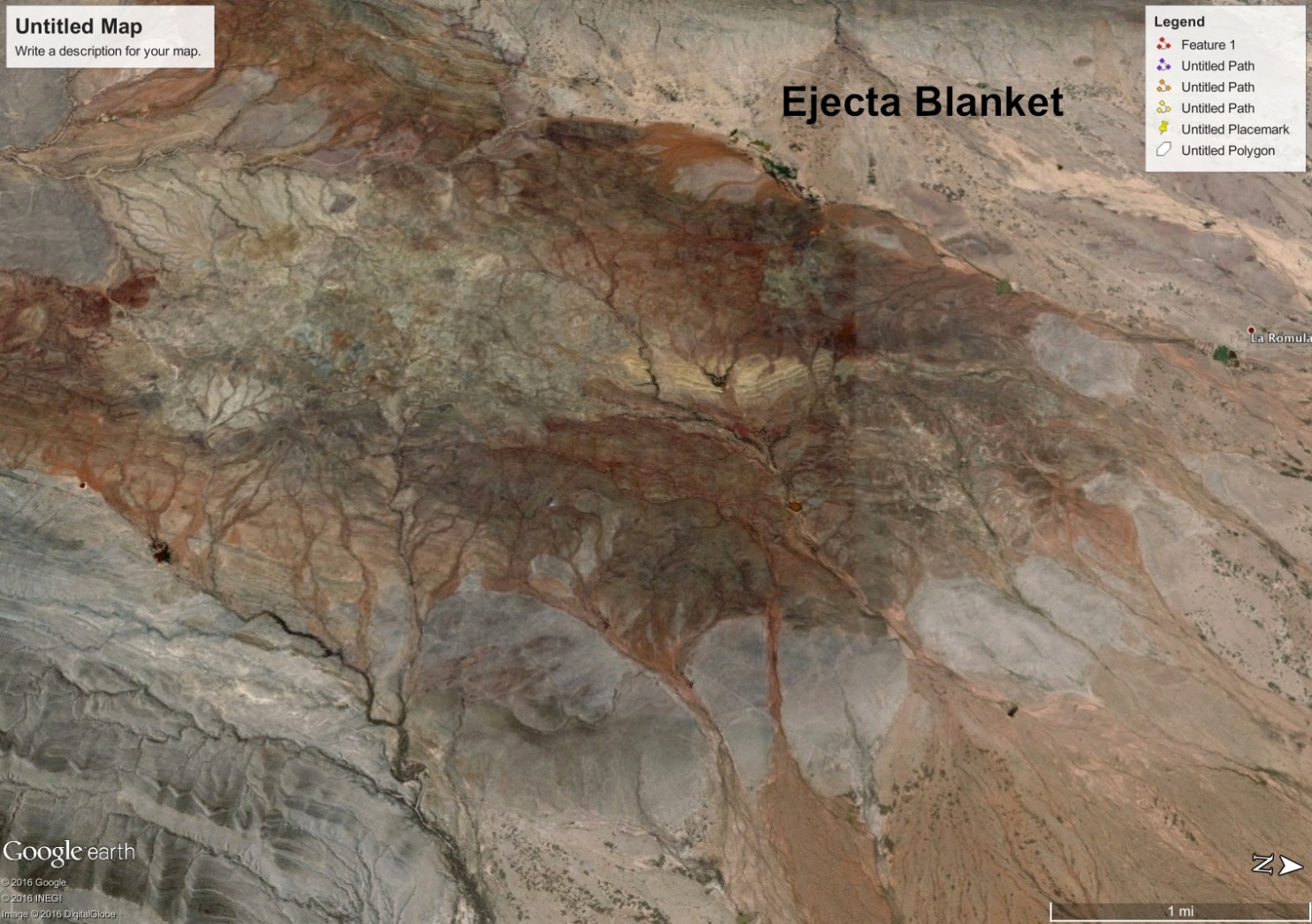
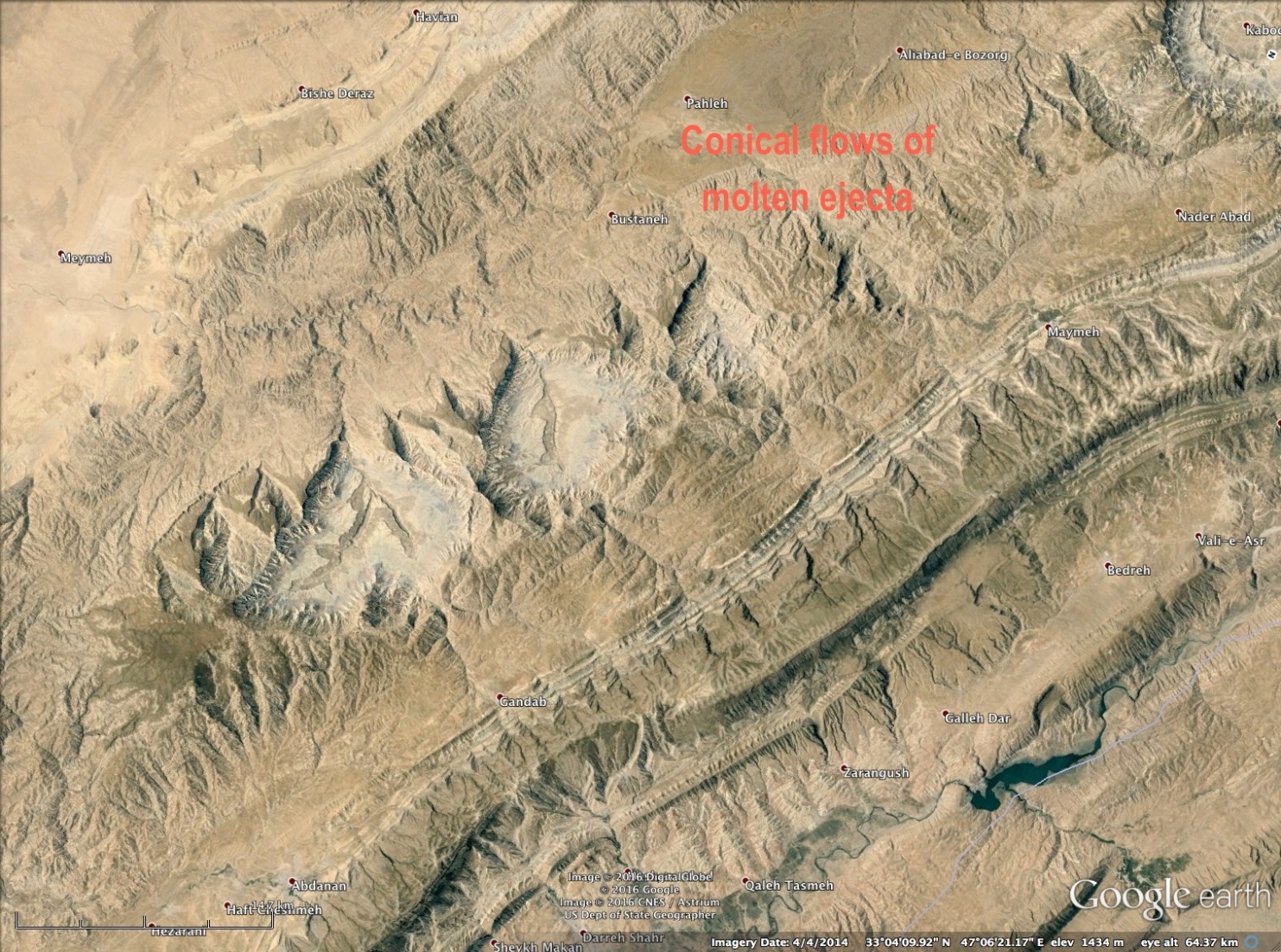
Material ablated from the blast forms layered hills and pressure ridges on the surrounding area. Layering indicates material was blown away from the blast, instead of being drawn toward it by the suction of the mushroom cloud. Evidence of high speed winds is seen where they form fingers of conical flow, dunes and pressure ridges.


Summary. . .
Let’s recap what we have seen:
1. Triangular buttresses form on the sides of mountains in the shape of reflected supersonic shock waves.
2. They are layered onto the mountain; so, they are not caused by seismic waves.
3. They are not layered sediments from an ancient beach, or waterway since the sharply angled triangles are a consistent feature around the world and do not conform to any motion of random water waves.
4. They are formed in all types of rock, including granite; so, they are not formed by eons of normal winds.
5. The triangular wave-forms exhibit compression and expansion from superimposed longitudinal and transverse waves.
6. The triangular wave forms exhibit harmonic repetition consistent with reflected shock waves.
7. The triangular wave-forms exhibit super-positioning and cancellation under compression consistent with reflected shock waves.
8. The triangular wave-forms are parallel to the primary shock pattern, consistent with reflected shock waves and perpendicular to the wind direction, consistent with supersonic winds created by a shock wave,
9. The triangular wave-forms exhibit less energy and more transient effects on softer substrates, and higher energy and sharper, more defined angles on hard substrates.
10. Triangular wave-forms exhibit transient reflections, normal shocks and features of density variation consistent with supersonic reflected shock waves.
11. The blast zones show concentric rings of pressure ridges, layered in the direction of the winds.
12. The winds within the blast zone are directed normal to the central mountain, or crater (outward blown winds,) as indicated by surface layering on pressure ridges and buttresses.
13. Boundary layer features of reflected waves can be found in the substrate of the blast zone as seen in the road cut in Iran.
14. Land surrounding the blast zone is blanketed with ejecta that exhibits flow patterns from high speed winds.
This concludes the Arc Blast series of articles on reflected shock waves and their significance. Future articles will examine more evidence for the effects of arc flash on the landscape:
- The ‘rooster tail’ and how big mountains are built
- Following winds and how Kelvin-Hemholtz instability can modify a mountain ridge
- Complex mountain forms and mountain arcs
- The interrelation between volcanoes and mountains
- The connection between shock waves, fractals and Lichtenburg landscapes
- How rocks form
- The cause and nature of an arc flash
- Sub-sea canyons, trenches and rifts
- Examples from the archaeological and mythological records of mankind
What is proposed here can be verified. In fact, mountains are the most tangible evidence for the Electric Universe model available. The evidence is under our feet. There are already reams of geologic data waiting to be re-interpreted. Geophysics, applied to evaluate geology as the consequence of electromagnetic and hydro-dynamic forces, will some day bear this out. You may even have the ability to bring that day closer. Your comments are invited.
Additional Resources:
The Arc-Blasted Earth | Space News
Arc Blast — Part One | Thunderblog
Andrew Hall is an engineer and writer, who spent thirty years in the energy industry. He was a speaker at the EU2016 conference and can be reached at hallad1257@gmail.com or https://andrewdhall.wordpress.com/
Disclosure: The proposed theory of arc flash and arc blast and their effects on the landscape are the sole ideas of the author, as a result of observation, experience in shock and hydrodynamic effects, and deductive reasoning. Dr. Mark Boslough’s simulation of an air burst meteor provided significant insight into the mechanism of a shock wave. His simulation can be viewed on YouTube: Mark Boslough. The author makes no claims that this method is the only way mountains or other geological features are created.
From Thunderbolts Info @ https://www.thunderbolts.info/wp/2016/05/11/arc-blast-part-1/ and https://www.thunderbolts.info/wp/2016/05/21/arc-blast-part-two/ and https://www.thunderbolts.info/wp/2016/05/28/arc-blast-part-three/
Thanks to: http://nexusilluminati.blogspot.com


 Sat Mar 23, 2024 11:33 pm by globalturbo
